foxBMS 2 TCP Step-by-Step Tutorial
This tutorial provides a structured bring-up workflow for the Ethernet and TCP path on a foxBMS 2 BMS-Master. It combines physical connection, software configuration, firmware start-up, and host-side validation into a reproducible engineering sequence. By following the phases, you can verify the link state, ICMP reachability, and the built-in TCP echo server from the first cable connection up to a confirmed payload exchange.
If you are commissioning a complete foxBMS 2 setup, start with the First steps with foxBMS 2 and then use this guide for the Ethernet and TCP-specific validation steps.
This tutorial describes an example setup of foxBMS 2 with the following parameters:
- 1 BMS-Master with RJ45 Ethernet connector
- foxBMS 2 source tree with TCP support enabled
- FreeRTOS+TCP stack initialized by the application
- Static IPv4 address
169.254.107.24 - TCP echo server on port
7 - 1 host PC connected over Ethernet
- Optional CAN monitoring of
f_BmsStatefor PHY status feedback
Phase 0 – Preparation
Documentation
For any changes or uncertainties within this tutorial, refer to these resources:
Recommended pages for this tutorial:
- Ethernet Module
- Network Interface
- How to Test TCP/IP
- How to Implement an Ethernet Port
- Building the application
- Debugging the application
- Connectors
- BMS-Masters overview
- Communication
Scope and Safety
- This tutorial is for skilled users validating a prototype Ethernet setup.
- Perform initial bring-up on a bench setup with known-good low-voltage power.
- Do not connect the controller to untrusted or routed networks.
- The built-in random-number hooks are not intended for security-relevant TCP exposure.
Tools
- BMS-Master with Ethernet-capable hardware revision
- Debugger for flashing or debugging the firmware or
- CAN interface for PC if CAN-based bootloader is already installed
- PC with foxBMS source and build environment
- Ethernet cable
- CAN interface for PC if you want to observe
f_BmsState - Terminal client such as PuTTY
- Optional packet capture tool such as Wireshark
Phase 1 – Understand the foxBMS TCP Path
Goal: Confirm the software path that has to work before testing on the bench.
Step 1.1 – Locate the Initialization Entry Point
foxBMS starts the Ethernet application from the main application start-up. When TCP support is enabled, main() calls ETH_Initialize().
The initialization sequence then performs these steps:
- Fill the network interface descriptor for the EMAC and PHY driver layer
- Fill the endpoint with the static network parameters
- Start the FreeRTOS+TCP stack with
FreeRTOS_IPInit_Multi()
Relevant files:
src/app/main/main.csrc/app/application/ethernet/ethernet.csrc/app/application/config/ethernet_cfg.c
Step 1.2 – Understand When the Server Tasks Start
The application does not create the TCP tasks during early start-up. Instead, FreeRTOS+TCP calls vApplicationIPNetworkEventHook_Multi() when the network changes state.
When the event is eNetworkUp, foxBMS creates:
- A queue for accepted sockets
ETH_ListenForConnection, which owns the listening socketETH_EchoServerInstance, which handles one accepted connection at a time
This means a successful PHY link and network-up event are prerequisites for the echo server test.
Step 1.3 – Understand the Runtime Connection Flow
The connection handling in src/app/application/ethernet/ethernet.c follows a simple pattern:
ETH_ListenForConnectioncreates a TCP socket.- The socket is bound to port
7and switched to listen mode. FreeRTOS_accept()waits for a client connection.- The accepted socket is placed into a queue.
ETH_EchoServerInstancereceives that socket from the queue.- Incoming data is read with
FreeRTOS_recv()and sent back withFreeRTOS_send(). - When the client closes or a timeout/error occurs, the socket is shut down and closed.
Keep this flow in mind during validation. A failure in any of these steps will show up as a missing ping response, no TCP handshake, or no echoed payload.
Phase 2 – Prepare the Hardware Link
Goal: Bring up a clean point-to-point Ethernet connection between the host PC and the BMS-Master.
Step 2.1 – Connect the RJ45 Connector
Use the RJ45 Ethernet connector (J2001) on the BMS-Master to connect the Ethernet cable.
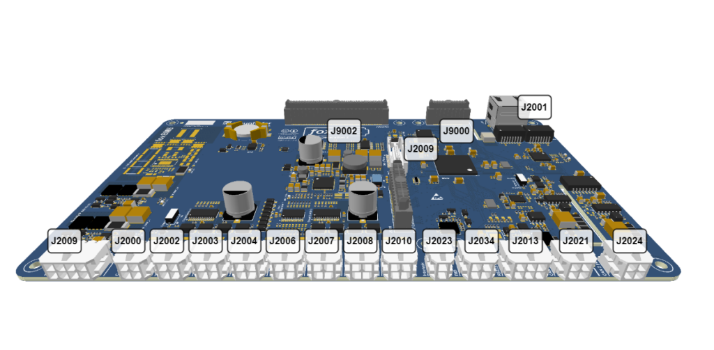
BMS-Master pinout
Step 2.2 – Check the PHY Hardware Note
If you are working with hardware version 1.2.3 or below, review the warning from the TCP/IP test documentation. In these versions, the PHY may be enabled by default and the pull-up resistors used to enable the PHY can interfere with Ethernet cable connection.
Resolve this hardware point before continuing.
Step 2.3 – Connect the Host PC Directly
Connect the host PC directly to the BMS-Master with an Ethernet cable. During bring-up, disconnect or temporarily disable other network adapters when possible, especially Wi-Fi, to avoid routing confusion on the host.
Step 2.4 – Prepare Optional CAN Monitoring
If you want additional visibility during link bring-up, monitor the CAN message f_BmsState. foxBMS publishes PHY alive and PHY linked status there, which is useful for separating physical-link problems from IP or socket problems.
Phase 3 – Configure the Software
Goal: Verify the default settings used by the foxBMS TCP tutorial setup.
Step 3.1 – Configure bms.json
The Ethernet initialization in main() is compiled only when FOXBMS_TCP_SUPPORT is enabled. Before testing, make sure your build configuration enables TCP support by adding the freertos-plus-tcp addon.
"rtos": {
    "name": "freertos",
    "addons": [
      "freertos-plus-tcp"
    ]
},
If this flag is disabled, the Ethernet module is not initialized and all later network tests will fail regardless of host configuration.
Step 3.2 – Verify the Static Network Parameters
The default endpoint configuration is stored in src/app/application/config/ethernet_cfg.c.
Default values:
- IP address:
169.254.107.24 - Netmask:
255.255.0.0 - Gateway:
169.254.107.1 - DNS server:
0.0.0.0 - MAC address:
00:08:EE:03:A6:6C
Because DHCP is disabled in the FreeRTOS IP configuration, foxBMS uses these static values during bring-up.
Step 3.3 – Verify Ping Support
In the current foxBMS FreeRTOS IP configuration, ipconfigREPLY_TO_INCOMING_PINGS is enabled and ipconfigUSE_DHCP is set to 0. Verify this in: src/os/freertos/freertos-plus/freertos-plus-tcp/source/include/FreeRTOSIPConfig.h
That means:
- The stack can respond to ICMP ping requests
- A static host-side IP setup is required for reliable testing
Step 3.4 – Verify the Echo Server Defaults
The echo server settings are defined in src/app/application/config/ethernet_cfg.h.
Important defaults for this tutorial:
- Server port:
7 - Backlog:
1 - Receive timeout:
portMAX_DELAY - Shutdown delay:
5000 ms - Sliding-window sizes are only relevant when
ipconfigUSE_TCP_WIN == 1
If you change the port or IP configuration, also update your host-side test steps accordingly.
Phase 4 – Build and Start foxBMS
Goal: Build firmware with the expected Ethernet/TCP configuration and start the system.
Step 4.1 – Build the Application
Build foxBMS with your normal workflow as described in the build documentation. Use the configuration that includes TCP support and the Ethernet application.
Step 4.2 – Flash and Start the Controller
Program the BMS-Master and start the application. The relevant software sequence for TCP start-up is:
- Hardware and operating-system initialization begins.
ETH_Initialize()seeds the random generator used by the TCP hooks.- The network interface descriptor is filled.
- The endpoint is filled with the static address set.
FreeRTOS_IPInit_Multi()starts the IP stack.- On link-up, the network event hook creates the listening and echo tasks.
Step 4.3 – Observe the Link State
After power-up and cable connection, verify that the PHY link is actually up.
Useful indicators are:
- PHY LED behavior on the hardware, if available
PhyLinked == 1inf_BmsState- Debug output from the network stack, if UART debug is enabled
If the link is not up, do not continue with ping or TCP tests yet.
Phase 5 – Configure the Host PC
Goal: Put the host PC into the same static subnet as foxBMS.
Step 5.1 – Assign a Static IPv4 Address
Assign the Ethernet adapter on the PC a static address in the link-local style subnet used by foxBMS, for example:
- IP address:
169.254.107.23 - Netmask:
255.255.0.0 - Gateway: leave empty or set consistently with your lab setup
Do not assign the foxBMS device address 169.254.107.24 to the host.
Step 5.2 – Minimize Host-Side Routing Ambiguity
During bring-up:
- Disable Wi-Fi if possible
- Disconnect unused VPNs or virtual adapters if they interfere with routing
- Use the Ethernet adapter directly connected to the BMS-Master for testing
Phase 6 – Validate ICMP Reachability
Goal: Confirm that the network interface and IP stack are working before moving to TCP.
Step 6.1 – Send a Ping
From a terminal on the host PC, send a ping to the foxBMS default IP address:
ping 169.254.107.24Expected result:
Pinging 169.254.107.24 with 32 bytes of data:
Reply from 169.254.107.24: bytes=32 time<1ms TTL=255
Reply from 169.254.107.24: bytes=32 time=1ms TTL=255
Reply from 169.254.107.24: bytes=32 time=1ms TTL=255
Reply from 169.254.107.24: bytes=32 time<1ms TTL=255
If ping fails, troubleshoot in this order:
- Check cable and link state.
- Confirm the host static IP configuration.
- Confirm
FOXBMS_TCP_SUPPORTis enabled. - Confirm the foxBMS IP address in
ethernet_cfg.c. - Confirm the hardware note for older PHY revisions.
Step 6.2 – Use Repeated Ping for Stability Checks
For a longer observation window, use a repeated ping count on the host system. This is useful after firmware changes, cable changes, or PHY debugging.
ping -t 169.254.107.24Phase 7 – Validate the TCP Echo Server
Goal: Confirm that TCP connection handling and data exchange work end to end.
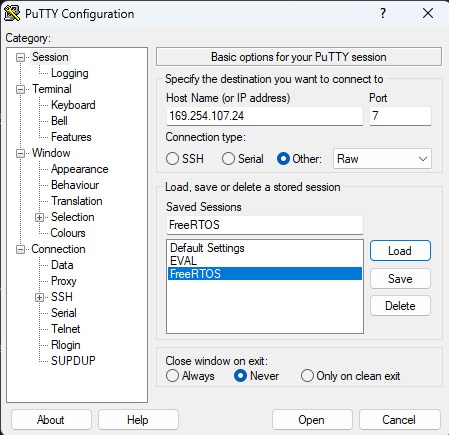
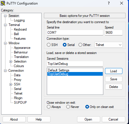
Step 7.1 – Configure PuTTY for a Raw TCP Session
Use PuTTY or a similar client with these settings:
- Host Name:
169.254.107.24 - Port:
7 - Connection type:
Raw
For better readability in the terminal:
- Enable implicit CR in every LF
- Enable implicit LF in every CR
Step 7.2 – Establish the TCP Connection
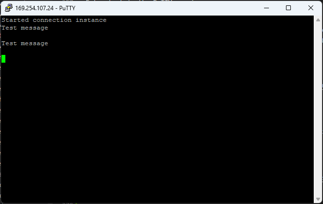
Open the connection from the host. When the connection succeeds, foxBMS accepts the socket in the listening task, passes it through the queue, and the echo server task starts handling the client. In the UART debug output, you should see:
Started connection instanceWith packet capture, the handshake should look similar to the following.

Step 7.3 – Send Test Payloads
Enter text in the PuTTY session. The echo server should return exactly the same payload.
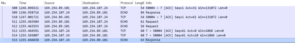
This mirrors the implementation in ETH_EchoServerInstance, where received bytes are sent back with FreeRTOS_send() until the full message has been transmitted.
The packet trace should look similar to the following.
Step 7.4 – Close the Session Cleanly
Close the client connection. foxBMS detects the shutdown, performs FreeRTOS_shutdown(), waits for the close sequence, and finally closes the socket.
The close handshake should look similar to the following.

Phase 8 – Debug via UART
Goal: Use the UART debugging interface for more insights.
Step 8.1 – Connect the Host PC via RS232
To connect the host PC via RS232, use the RS232 connector (J2013) on the BMS-Master board. The pinout is described in the picture below. Connect this to a USB-RS232 adapter.
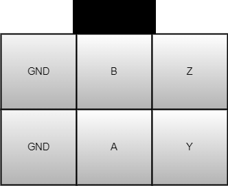
For RS232 only the pins from the lower row are necessary.
Step 8.2 – Configure RS232 Debugging
For UART debug, add uart as a debugging interface in bms.json:
"debug": {
    "interfaces": [
      "uart"
    ]
},
This enables the default TCP logging via UART.
Step 8.3 – Use Serial Terminal to Establish Connection
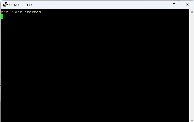
Open a serial terminal with the correct COM port selected and a baud rate of 9600 baud.
When starting foxBMS with TCP enabled, it should display:
Phase 9 – Troubleshooting by Symptom
Goal: Narrow failures to the correct layer quickly.
Step 9.1 – Link Does Not Come Up
Focus on:
- Hardware revision note for PHY pull-up resistors
- Cable and connector integrity
- PHY alive and linked status on CAN
- Board-level power and Ethernet hardware status
Step 9.2 – Link Is Up but Ping Fails
Focus on:
- Static IP settings on both sides
ethernet_cfg.caddress valuesFreeRTOSIPConfig.hping and DHCP configuration- Whether the Ethernet module is compiled into the application
Step 9.3 – Ping Works but TCP Fails
Focus on:
- Port configuration in
ethernet_cfg.h - Whether the network-up hook created the listening and echo tasks
- Host tool configuration using raw TCP on port
7 - Packet capture to check whether the TCP handshake completes
Step 9.4 – TCP Connects but No Data Is Echoed
Focus on:
- Whether the client is sending raw data rather than a protocol wrapper
- Receive/send debug logs if enabled
- Socket timeout behavior
- The queue handoff between accept and the echo task
Summary
This tutorial validates the foxBMS TCP path in the same order the software uses it:
- Enable and initialize the Ethernet stack.
- Bring the PHY link up.
- Confirm ICMP ping reachability.
- Connect to the built-in echo server on port
7. - Confirm payload echo and clean connection shutdown.
Once these steps pass, the foxBMS Ethernet base path is ready for further application-level TCP development.
Warning: The foxBMS 2 platform including the foxBMS 2 hardware and the foxBMS 2 software are under permanent development. The free and open research and development platform foxBMS 2 as presented in the documentation hereafter is not provided to be used without any adaptions (e.g., to fulfill mandatory regulations) in consumer products, electric vehicles, production environments or any similar usages: the open source version of the foxBMS 2 platform is only intended to be used by skilled professionals trained in designing battery system prototypes.
In case you encounter problems, please contact us.
The Fraunhofer IISB foxBMS Team