First steps with foxBMS 2
- 1 BMS-Master
- 6 BMS-Slaves (NXP MC33775A)
- 1 string
- 14 cell measurements per BMS-Slave
- 8 temperature measurements per BMS-Slave
- Insulation monitoring via Bender ir155
- String current measurement via Isabellenhuette IVT-S
Battery system setup (single string)
Phase 0 – Preparation
Documentation
For any changes or uncertainties within this tutorial, refer to these resources:
Recommended pages for this tutorial:
- Safety
- First steps on hardware
- Configuration
- Building the application
- Bootloader
- Debugging the application
- Connectors
- BMS-Masters overview
- BMS-Slaves overview
- BMS-Interfaces overview
- System voltage and current monitoring
- Precharging
- IMD testing
- Communication
Scope and Safety
- This tutorial is for skilled users in the battery systems domain validating a prototype setup.
- Perform initial commissioning with current-limited sources and an emergency disconnect path.
- Before enabling HV, verify all low-voltage checks in Phase 6 are passing.
Tools
When not using a version pre-flashed with the CAN-based bootloader or for debugging purposes:
- Debugger (for example Lauterbach)
- CAN interface for PC
- PC with:
- foxBMS source (cloned from official repository)
- foxBMS toolchain (see documentation)
- Optional: VS Code for editing/configuration
foxBMS Components
The following overview shows the key foxBMS hardware components used in this tutorial setup.
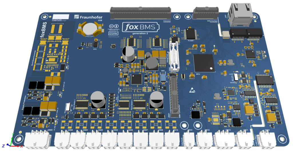 BMS-Master |
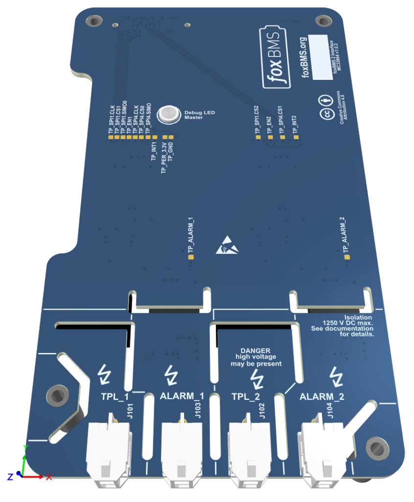 MC33664-based BMS-Interface |
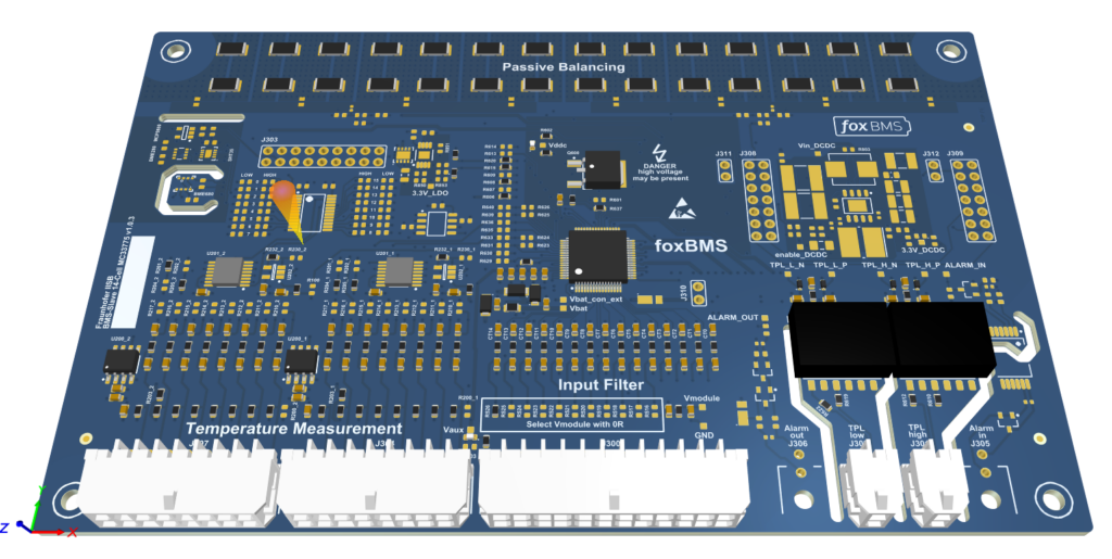
MC33775A-based BMS-Slave
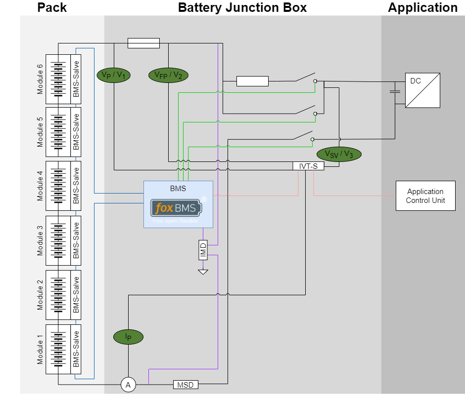
Phase 1 – High-Voltage Power Path
Goal: Build the power path for one string with 3 contactors, IVT-S, and voltage measurement.
Step 1.1 – Choose 3-Contactor Topology
Use the standard layout:
- Main- contactor in the negative line between pack- and system negative
- Precharge contactor in the positive line with a series precharge resistor
- Main+ contactor in the positive line between pack+ and system positive
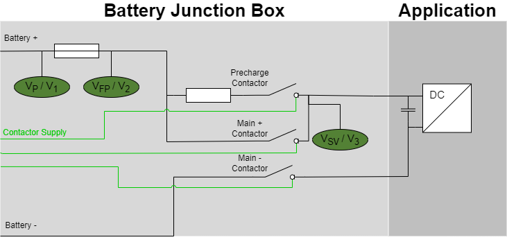
Contactor topology
Reference: Precharging
Step 1.2 – Install IVT-S Current Sensor
Place the IVT-S in series with the string current path, recommended in the pack negative line:
Battery- -> IVT-S -> Main- contactor -> System-
Further notes:
- Provide IVT-S supply according to its datasheet
- Ensure IVT-S ground is consistent with system grounding (check IVT-S manual)
Step 1.3 – Define Voltage Measurement Points
The voltage measurement points are placed as shown in the image above:
- Voltage1 (V1): pack voltage (battery+ vs battery-)
- Voltage2 (V2): optional (for example after fuse) or unused
- Voltage3 (V3): DC-link voltage (after Main+ / precharge)
Step 1.4 – Install Bender ir155 Insulation Monitoring Device
Install the Bender ir155 according to its manual in the HV system.
Phase 2 – BMS-Master Connectors
Goal: Connect power supply, contactors and communication BMS-Master connectors.
Use the BMS-Master hardware manual, section “Connectors”, for exact connector IDs and pin numbers.
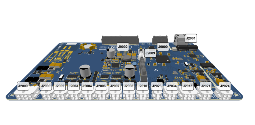
BMS-Master pinout
| Connector ID | Functionality | Pinout |
|---|---|---|
| J3008 | Debugger | Debug Connector |
| J2009 | Supply | Supply |
| J2000 | Smart Power Switch 0 (Contactor 0) | Smart Power Switches |
| J2001 | RJ45 Ethernet Connector | RJ45 Ethernet Connector |
| J2002 | Smart Power Switch 1 (Contactor 1) | Smart Power Switches |
| J2003 | Smart Power Switch 2 (Contactor 2) | Smart Power Switches |
| J2004 | Smart Power Switch 3 (Contactor 3) | Smart Power Switches |
| J2006 | Smart Power Switch 4 (Contactor 4) | Smart Power Switches |
| J2007 | Smart Power Switch 5 (Contactor 5) | Smart Power Switches |
| J2008 | Smart Power Switch 6 (Contactor 6) | Smart Power Switches |
| J2010 | Smart Power Switch 7 (Contactor 7) | Smart Power Switches |
| J2033 | Interlock | Interlock |
| J2034 | PWM (Insulation Monitoring) | Insulation Monitoring |
| J2013 | RS232 | RS485 |
| J2021 | CAN 1 | CAN1 |
| J2024 | CAN 2 (isolated) | CAN2 (isolated) |
References:
Step 2.1 – Wire Power Supply
Wire the low-voltage power supply to the BMS-Master according to the hardware manual.
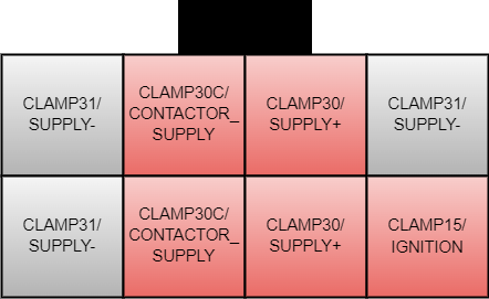
BMS-Master power supply connector
Pin description (receptacle view, as shown in the image):
CLAMP30 / SUPPLY+(2 pins): main positive low-voltage supply input for the BMS-Master electronics.CLAMP31 / SUPPLY-(3 pins): supply return/ground reference.CLAMP30C / CONTACTOR_SUPPLY(2 pins): positive supply rail for contactor coil driving.CLAMP15 / IGNITION(1 pin): ignition/wake input used to enable system startup behavior.
Before first power-up, verify polarity and wiring continuity with a multimeter. It’s essential that your power supply provides a steady current of at least 2 A.
Insufficient current can lead to unexpected errors when switching the contactors.
Step 2.2 – Connect Debugger
Connect your debugger to the 38-pole Mictor connector (J3008) on the BMS-Master. Use the pinout from the hardware manual.
Step 2.3 – Wire Contactor Outputs
Find the contactor/power output connector on the BMS-Master.
Wire as follows:
- foxBMS output assigned to
MAIN_PLUS-> Main+ contactor coil driver (J2000 | Smart Power Switch 0 (Contactor 0)) - foxBMS output assigned to
MAIN_MINUS-> Main- contactor coil driver (J2002 | Smart Power Switch 1 (Contactor 1)) - foxBMS output assigned to
PRECHARGE-> Precharge contactor coil driver (J2003 | Smart Power Switch 2 (Contactor 2)) - foxBMS output assigned to
MAIN_PLUS-> Main+ contactor coil driver (J2004 | Smart Power Switch 3 (Contactor 3))
Ensure:
- Proper coil supply (often 12 V or 24 V)
Step 2.4 – Wire CAN Bus
Locate the BMS-Master CAN 1 connector (J2021).
Connect:
- IVT-S CAN to CAN 1 of the BMS-Master
- Application Control Unit CAN to the same bus
Terminate bus ends with 120 Ohm.
General CAN bus guidelines:
- Use a linear bus topology (no star topology for main trunk wiring).
- Place exactly two
120 Ohmtermination resistors: one at each physical end of the bus. - Keep stub lines to each node short.
- Use twisted pair wiring (
CAN_HandCAN_L) and keep polarity consistent across all nodes. - Ensure all nodes use the same baud rate (for this setup:
500 kbit/s). - Provide a proper common reference between nodes (ground strategy per system design).
- Route CAN lines away from high-current switching paths when possible.
- For an unpowered bus with both terminations installed, measure about
60 OhmbetweenCAN_HandCAN_Las a quick sanity check.
Reference: Communication
Phase 3 – BMS-Slave Hardware (6x MC33775A via MC33664)
Goal: Realize one string with 6 BMS-Slaves, each monitoring 14 cells (84 cells total), and wiring 8 temperature sensors.
Step 3.1 – Connect the BMS-Master to MC33664-based BMS-Interface
Place the MC33664 interface board on the BMS-Master as shown in the picture and tighten the screws
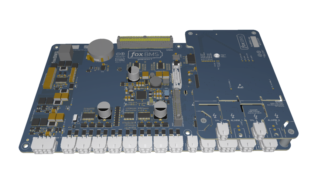
BMS-Master with mounted BMS-Interface
References:
Step 3.2 – BMS-Master to First MC33775A-based BMS-Slave
Connect TPL_1 with TPL High of the BMS-Slave using the twisted pair cable. Ensure TPL High and TPL Low are not swapped.
Step 3.3 – Daisy-Chain 6 BMS-Slaves
From MC33775A #1 to MC33775A #2
TPL LOW->TPL HIGH
Repeat until MC33775A #6.
Step 3.4 – Cell Voltage Wiring (14 Cells per BMS-Slave)
For Connect the cell connector as shown in the picture below for all cells:
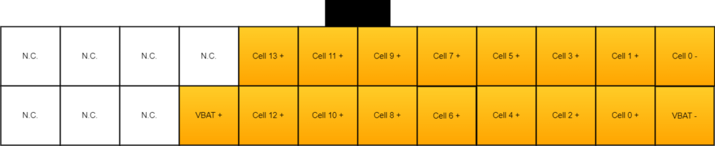
BMS-Slave cell voltages connector
- Wire up to 14 cells:
- BMS-Slave 1: Cells 1-14
- BMS-Slave 2: Cells 15-28
- BMS-Slave 3: Cells 29-42
- BMS-Slave 4: Cells 43-56
- BMS-Slave 5: Cells 57-70
- BMS-Slave 6: Cells 71-84
Step 3.5 – Temperature Sensors (8 Used)
In this example, 8 temperature sensors are used while 16 are possible.
On each BMS-Slave, connect the temperature sensors as shown in the image.
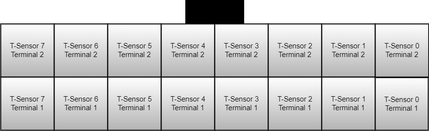
BMS-Slave temperature sensors connector
Step 3.6 – Interlock
Make sure the interlock circuit (J2033) is closed by either:
- Connecting a bridge dongle for testing
- Fully connecting everything needed in the actual system
Phase 4 – BMS Configuration
Now tailor the foxBMS firmware to your exact system. For installation of the foxBMS toolchain refer to the Software Installation documentation.
File names and exact symbols differ between foxBMS versions. Use these as patterns and search the repository for similar names.
Step 4.1 – Configure bms.json
The conf/bms/bms.json file allows configuration of basic functions that compile different sources. Every option not mentioned in this tutorial can remain at defaults.
Configure the application current sensor (default IVT-S):
"current-sensor": {
  "type": "can",
  "manufacturer": "isabellenhuette",
  "model": "ivt-s"
}
For insulation monitoring, select:
"insulation-monitoring-device": {
  "type": "pwm",
  "manufacturer": "bender",
  "model": "ir155"
}
Configure BMS slave analog front-end:
"analog-front-end": {
  "ic": "mc33775a",
  "manufacturer": "nxp"
}
Reference: Configuration
Step 4.2 – System Topology (Strings, BMS-Slaves, Cells)
In the battery system configuration in src/app/application/config/battery_system_cfg.h:
- Set 1 string
- Set 6 BMS-Slaves per string
- Set 14 cells per BMS-Slave
- Set 8 temperature sensors
Simplified example:
#define BS_NR_OF_STRINGS                  (1u)
#define BS_NR_OF_MODULES_PER_STRING       (6u)
#define BS_NR_OF_CELL_BLOCKS_PER_MODULE   (14u)
#define BS_NR_OF_TEMP_SENSORS_PER_MODULE  (8u)
Step 4.3 – Current Sensor
Define whether discharge current is positive or negative:
#define BS_POSITIVE_DISCHARGE_CURRENT (true)Step 4.4 – Temperature Sensor
Adapt the supply voltage of the resistor divider for your temperature sensor to the supply voltage of your BMS-Slave (see docs):
#define TS_EPCOS_B57251V5103J060_RESISTOR_DIVIDER_SUPPLY_VOLTAGE_V (5.0f)Therefore:
- Search for your temperature sensor name in
bms.json - Find the corresponding sensor file, for example
epcos_b57251v5103j060.h
Step 4.5 – Contactor Mapping
Set the correct number of contactors in battery_system_cfg.h. foxBMS generally calculates 2 contactors per string. With one extra precharge contactor, add one contactor outside strings:
#define BS_NR_OF_CONTACTORS_OUTSIDE_STRINGS (1u)In contactor configuration (for example contactor_cfg.c):
{
    CONT_SWITCH_OFF,
    CONT_SWITCH_OFF,
    CONT_FEEDBACK_NORMALLY_OPEN,
    BS_STRING0,
    CONT_PLUS,
    SPS_CHANNEL_0,
    CONT_CHARGING_DIRECTION
},
{
    CONT_SWITCH_OFF,
    CONT_SWITCH_OFF,
    CONT_FEEDBACK_NORMALLY_OPEN,
    BS_STRING0,
    CONT_MINUS,
    SPS_CHANNEL_1,
    CONT_DISCHARGING_DIRECTION
},
/* Precharge contactor configuration */
{
    CONT_SWITCH_OFF,
    CONT_SWITCH_OFF,
    CONT_HAS_NO_FEEDBACK,
    BS_STRING0,
    CONT_PRECHARGE,
    SPS_CHANNEL_2,
    CONT_BIDIRECTIONAL
},
Reference: Precharging
Phase 5 – Build and Flash (Bootloader + Application)
Step 5.1 – Build Bootloader
If no bootloader is pre-installed in the BMS-Master, compile and flash it first:
.\fox.ps1 waf build_bootloader_embeddedReferences:
Step 5.2 – Flash Bootloader
- Connect debugger to the debug connector (J3008).
- In debugger software:
- Load bootloader binary.
- Program designated bootloader flash region.
- Power-cycle.
Step 5.3 – Build Main Application
Open a terminal in a foxBMS repository checkout.
- Configure project:
.\fox.ps1 waf configure - Build application: \fox.ps1 waf build_app_embedded
References:
Step 5.4 – Flash Main Application
With the debugger:
- Program application binary into the application flash region
- Optionally script bootloader + application flashing if supported
With Bootloader:
- Power down foxBMS
- Check the status of the bootloader:
.\fox.ps1 bootloader check - If it says
Waiting bootloader to be powered on … - Upload a new foxBMS 2 application into the flash memory of BMS-Master:
.\fox.ps1 bootloader load-app - Power on foxBMS
- When upload complete, reboot foxBMS
Phase 6 – Bring-Up Checklist
Low-Voltage Only
- Connect LV supply connector
- Power the BMS-Master and the BMS-Slaves with LV supply (no HV)
- Expected current consumption is around
250 mAwhen software is flashed - Confirm foxBMS debug LED:
- Normal:
500 ms - Error:
100 ms
- Normal:
CAN
- Connect only
CAN1to the PEAK PCAN adapter - Check whether CAN messages are received at
500 kbit/s - Transmit CAN message
foxBMS_BmsStateRequestwithRequestBmsMode=Standbyin a period of 100 ms - Verify state transition by observing
f_BmsState
Reference: Communication
BMS-Slaves (6x MC33775A)
- Confirm the BMS reports correct cell voltages
- Confirm 8 temperature readings are available
Precharge and Contactors (with controlled HV)
Request DISCHARGE mode. and observe the sequence:
- Main- closes
- Precharge closes
V_BUSrises and approachesV_PACK- Main+ closes, precharge opens
Monitor the current via IVT-S.
Reference: System voltage and current monitoring
Suggested Acceptance Criteria
- No persistent software error state after
STARTUPand mode requests - All 84 cell voltages plausible and without open-wire-like outliers
- All configured temperature channels update and remain plausible
- Precharge reaches a stable DC-link voltage before Main+ closes
- IMD status remains valid during LV and HV operation
Warning: The foxBMS 2 platform including the foxBMS 2 hardware and the foxBMS 2 software are under permanent development. The free and open research and development platform foxBMS 2 as presented in the documentation hereafter is not provided to be used without any adaptions (e.g., to fulfill mandatory regulations) in consumer products, electric vehicles, production environments or any similar usages: the open source version of the foxBMS 2 platform is only intended to be used by skilled professionals trained in designing battery system prototypes.
In case you encounter problems, please contact us.
The Fraunhofer IISB foxBMS Team