Overview of the Technical Specifications
Hereafter a general overview giving the technical specifications of the foxBMS ecosystem is presented. The complete detailled documentation is available on Read The Docs.
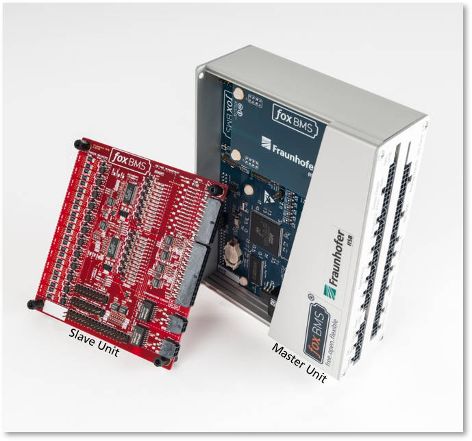
The foxBMS consists of 4 board types:
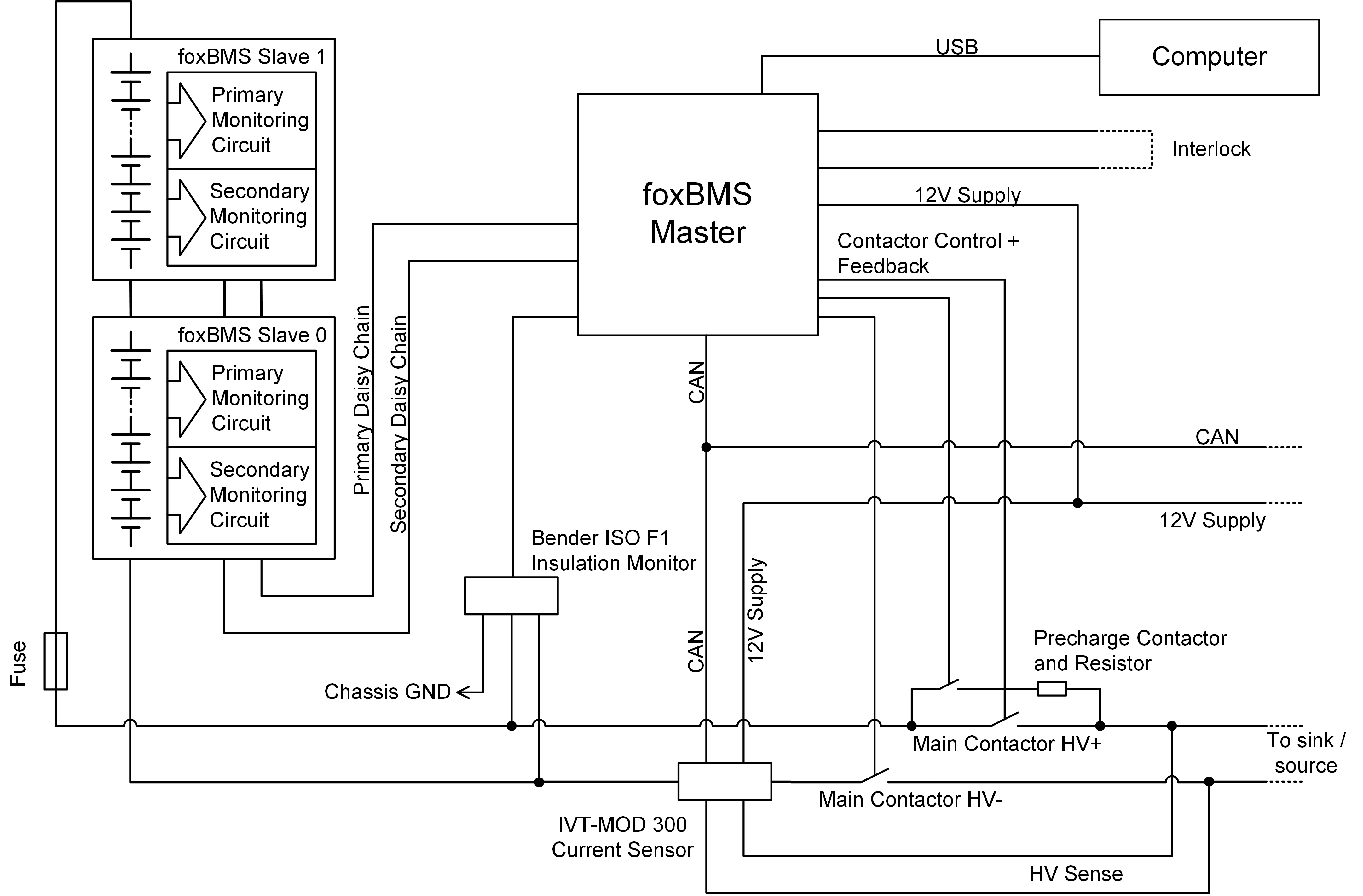
The battery modules (or pack) connect and disconnect from the load via three power contactors (i.e., relays):
- Main Contactor Plus
Main Contactor Minus
Pre-charge Contactor
MCU0 drives these contactors. Requests are made via CAN to the system to open and close the contactors. Based on the measurements and the algorithms in the software, MCU0 decides if the contactors should be closed or opened. It sends information via CAN so that the user knows the state of the system.
An interlock line is also present. If it is opened, either by MCU0, MCU1 or somewhere else (e.g., emergency stop), all contactors will immediately open.
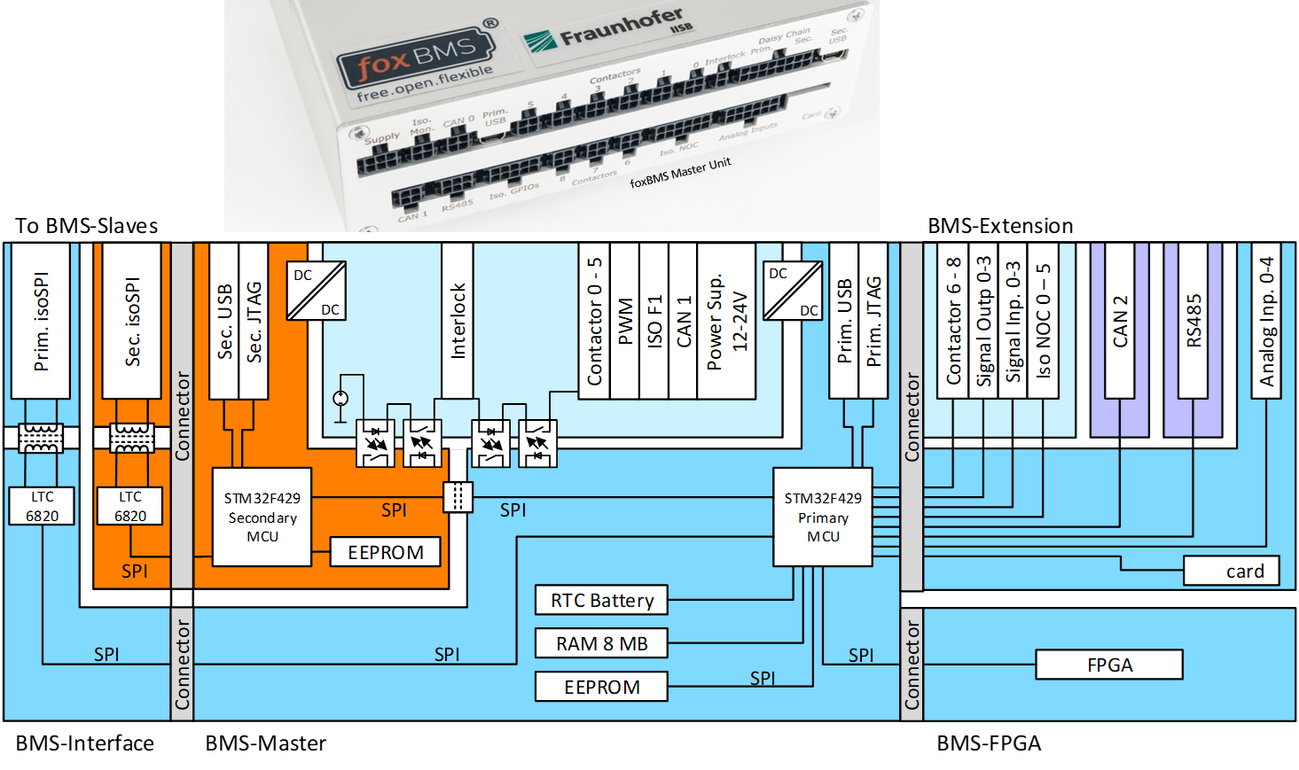
foxBMS BMS-Master Board
The BMS-Master Board implements two ARM-based microcontroller units (ARM Cortex-M4F MCUs): MCU0 (also called Primary MCU) and MCU1 (also called Secondary MCU). The BMS software runs on MCU0, while MCU1 provides the required redundant safety during the software development process.
MCU0 communicates with the outside world via a CAN bus (CAN0). A shunt based current sensor connected to the CAN bus measures the current flowing through the entire battery system. MCU0 controls the current sensor via the internal CAN and sends the resulting measurements over the external CAN.
A secondary ARM-based microcontroller is present on the BMS-Master, called MCU1 (or secondary MCU). It monitors the Slave Units via a second and independent daisy chain. Like the MCU1, it can open the interlock in case something goes wrong with the system.
| Parameter / Connector | Description |
|---|---|
| Board Size | 160mm x 120mm |
| Operating Temperature Range | -40°C to +85°C |
| Power Supply | 12V-24V 150 mA @ 12V 110 mA @ 24 V |
| Primary USB | Galvanically isolated USB connector to flash the MCU0 |
| Secondary USB | Galvanically isolated USB connector to flash the MCU1 |
| CAN0 | First galvanically isolated CAN interface. |
| Contactors (6x) | 6 contactors with auxiliary contacts acting as contactor state feedback can be connected to the BMS-Master |
| MCU0 | ARM Cortex-M4 STM32F429IIT6 (primary) Runs the applications. Can open the interlock. |
| MCU1 | ARM Cortex-M4 STM32F429VIT6 (secondary) Used for redundant safety software, has a dedicated daisy-chain to communicate independently with the Slave Units. Can open the interlock. |
| Memory | 256kB EEPROM with ECC for the storage of safety critical battery parameters 4kB of Backup-SRAM storing battery state parameters and diagnostic messages, supplied by a battery coin cell. 8MB SDRAM |
foxBMS BMS-Extension Board
Because of the smart partionning developed for foxBMS, the BMS-Extension Board provides more inputs and outputs, thus enabling further functions and rapid adaption to specific needs.
This description reflects the free and open source version of foxBMS. Due to the open nature of the system, many other possibilities exist, like for example:
- Use of other types of current sensors (e.g., shunt-based or Hall-effect based)
- Use of no foxBMS Slave Units: the BMS Master Unit performs a direct measurement of the cell voltages and cell temperatures
- Control of a higher number of contactors (e.g., up to 9)
| Parameter / Connector | Description |
|---|---|
| Board Size | 160mm x 120mm |
| Operating Temperature Range | -40°C to +85°C |
| CAN1 | Second galvanically isolated CAN interface. |
| RS485 (1x) | Galvanically isolated differential RS485 series interface to be used with RS485 compliant equipment. |
| Isolated GPIOs (8x) | Galvanically isolated general purpose inputs (4x) and outputs (4x). |
| Contactors (3x) | Additionnally to the 6 contactor connectors on the BMS-Master, 3 more contactors with auxiliary contacts acting as contactor state feedback can be connected to the BMS-Extension. |
| NOC (6x) | Galvanically isolated normally open contacts |
| Analog Inputs (5x) | Analog inputs to sample voltages (not isolated galvanically) |
| Memory Card | Connector on which a NAND Flash based memory card can be connected in SPI mode |
foxBMS BMS-Interface Board
An interface board called BMS-Interface performs the signal conversion between the SPI interfaces of both microcontrollers on the BMS-Master and the foxBMS Slave Units. The BMS-Interface converts the SPI signals from the BMS-Master Board into differential signals used by the daisy chain connecting the BMS-Slave boards. WIth the monitoring ICs from Analog Devices (former Linear Technology) LTC6804, LTC6811 and LTC6813, the number of BMS-Slave Boards connected in a single daisy chain is virtually unlimited. However, the reading out time increases proportionally with the number of BMS-SLave Boards in the daisy chain.
foxBMS BMS-Slave Board
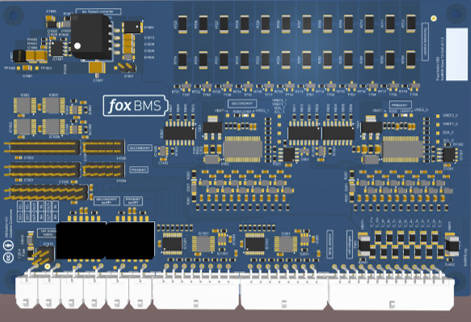
The foxBMS Slave Unit (BMS-Slave Board) measures the cell voltages and cell temperatures in each battery module. The foxBMS Slave Units connect to each other via a proprietary daisy chain from Analog Devices (former Linear Technology) called isoSPI. The following table shows the detailed technical specifications:
| Parameter / Connector | Description | Description |
|---|---|---|
| Monitoring IC | LTC6811-1 (formerly LTC6804-1) | LTC6813-1 |
| Maximum number of BMS-Slave in a single daisy chain | Virtually unlimitted (no addressing) | Virtually unlimitted (no addressing) |
| Communication interface between BMS-Slave and BMS-Interface on the Master Unit | isoSPI (proprietary differential daisy-chain communication interface from Analog Devices, formerly Linear Technology) at 1Mb/s with functional isolation up to 1600Vdc working voltage Currently not enabled for reverse isoSPI | isoSPI (proprietary differential daisy-chain communication interface from Analog Devices, formerly Linear Technology) at 1Mb/s with functional isolation up to 1600Vdc working voltage Enabled for reverse isoSPI to provide a backup path in case a daisy-chain connection is broken |
| Cell voltage measurements | 12 cell voltage sensing in the 0-5V range | 18 cell voltage sensing in the 0-5V range |
| Voltage measurement accuracy | ±2.8mV on cell level (in filtered mode with 16bit sampling in the -40°C to +125°C temperature range) ±0.25% on module level | ±4.2mV on cell level (in filtered mode with 16bit sampling in the -40°C to +125°C temperature range) ±0.35% on module level |
| Temperature measurements | 8 temperature sensors (NTC 10kOhms) preconfigured (8 more can be added via implemented multiplexer for a total of 16 temperature sensors per BMS-Slave) | 8 temperature sensors (NTC 10kOhms) preconfigured (8 more can be added via implemented multiplexer for a total of 16 temperature sensors per BMS-Slave) |
| Measurement speed | 20ms for a pack with 8 modules with 12 cells per module (i.e., 50Hz cell voltage refresh rate with a pack with 96 cells) which corresponds to 2.5ms per module with 12 cells | To be investigated (expected: approximately 3.75ms per 18 cells module) |
| Power supply | At least 11V are needed if supplied only by the module itself | At least 16V are needed if supplied only by the module itself |
| Number of cells that can be monitored with one BMS-Slave | 4 to 12 cells if the module self supplying is used 1 to 12 cells if the external power supply connection is used | 6 to 18 cells if the module self supplying is used 1 to 18 cells if the external power supply connection is used |
| Optional external power supply voltage range (instead of using the battery module energy) | 12V-24V | 12V-24V |
| Balancing | Passive balancing (36 Ohms / 100mA) using discrete PMOS and with global opto-coupler feedback function | Passive balancing (36 Ohms / 100mA) using discrete PMOS and with global opto-coupler feedback function |
| Module local data storage | 256kB EEPROM M95M02 (2Mbit, I2C interface) with ECC function storing min and max values of cell voltages, temperatures and other log data | 256kB EEPROM M95M02 (2Mbit, I2C interface) with ECC function storing min and max values of cell voltages, temperatures and other log data |
| Current consumption at 25°C | <50mA (ON) ; <30µA (SLEEP) | <50mA (ON) ; <30µA (SLEEP) |
| Fuse protection in case of wrong connection in the laboratory | Every sense line (13) and power line (2) is fused (15 fuses) | Every sense line (19) and power line (2) is fused (21 fuses) |
| Functional safety levels | Concept allowing adapted designs to reach safety levels up to SIL3 / ASIL-D / DAL-B even in 24/7 applications, including fault detection and compensation (these functional safety levels are not reached with the free online versions!) | Concept allowing adapted designs to reach safety levels up to SIL3 / ASIL-D / DAL-B even in 24/7 applications, including fault detection and compensation (these functional safety levels are not reached with the free online versions!) |
| Additionnal functions | Multiplexers and port expander offering more flexibility for your applications | Multiplexers and port expander offering more flexibility for your applications |